Tutorial : other materials - birefringent materials
Birefringence
Unlike homogeneous (isotropic) materials, optical properties of birefringent (anisotropic) materials depend on the direction of propagation. Because of their effect on light propagation and polarization, anisotropic materials are used in many optical components as polarizers, retarder plates, birefringent filters, beam splitters,....
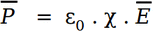
In homogeneous materials, electromagnetic waves "see" the same refraction index whatever their propagation direction. It is because electric field  , electric induction
  and polarization
  are parallel :
 .
χ is the electromagnetic susceptibility.
In birefringent materials, because atoms arrangements have their own symetries, the polarization "sensitivity" to an electric field depends on the electric field direction. Therefore, except in particular cases, the polarization and the electric field are not parallel. The first relation above is changed in :
.
χ is the electromagnetic susceptibility.
In birefringent materials, because atoms arrangements have their own symetries, the polarization "sensitivity" to an electric field depends on the electric field direction. Therefore, except in particular cases, the polarization and the electric field are not parallel. The first relation above is changed in :
 .
.
 is a 3 X 3 tensor.
The electric induction , which is parallel to the electric field in an homogeneous material, can be written :
is a 3 X 3 tensor.
The electric induction , which is parallel to the electric field in an homogeneous material, can be written :
 .
.
 is the "identity" tensor.
More commonly, this relation can be written
is the "identity" tensor.
More commonly, this relation can be written 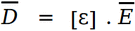 .
.
 is the dielectric tensor.
As a consequence, the Poynting vector (giving the direction of the light ray) remains perpendicular to the electric field and is in general no more parallel to the wave vector (giving the propagation direction of the wave) that remains perpendicular to the electic induction.
Because of the atoms arrangement symetries, the dielectric tensor has less than 9 undependant coefficients. In a particular coordinate system referred to symetry axis of the material (optical axis), it can be diagonalized as follows :
is the dielectric tensor.
As a consequence, the Poynting vector (giving the direction of the light ray) remains perpendicular to the electric field and is in general no more parallel to the wave vector (giving the propagation direction of the wave) that remains perpendicular to the electic induction.
Because of the atoms arrangement symetries, the dielectric tensor has less than 9 undependant coefficients. In a particular coordinate system referred to symetry axis of the material (optical axis), it can be diagonalized as follows :
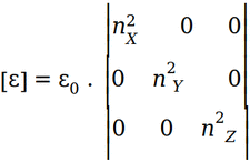 .
nX, nY and nZ are the refraction indexes respectively related to the X, Y and Z axis.
The resolution of Maxwell equations shows that for a given pulsation ω and a given wave direction, there are two solutions giving two possible values for the wave vector and therefore of the refraction index n, each solution having different linear polarization.
Indeed, the two values of the refraction index n are given by the equation :
.
nX, nY and nZ are the refraction indexes respectively related to the X, Y and Z axis.
The resolution of Maxwell equations shows that for a given pulsation ω and a given wave direction, there are two solutions giving two possible values for the wave vector and therefore of the refraction index n, each solution having different linear polarization.
Indeed, the two values of the refraction index n are given by the equation :
 .
The associated electrield field is :
.
The associated electrield field is :
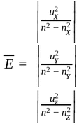 .
uX, uY, uZ are the coordinates of the unitary vector
.
uX, uY, uZ are the coordinates of the unitary vector  giving the direction of propagation.
This formuma is only valid in the general case for n different from nX, nY and nZ.
There are two main types of birefringent materials : uniaxial and biaxial materials.
The biaxial materials are corresponding to the general case presented above and will not be discussed further.
giving the direction of propagation.
This formuma is only valid in the general case for n different from nX, nY and nZ.
There are two main types of birefringent materials : uniaxial and biaxial materials.
The biaxial materials are corresponding to the general case presented above and will not be discussed further.
Uniaxial material
For uniaxial materials, the dielectric tensor is :
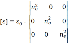 .
The crystal axis ( optical axis ) is the Z axis. no is said the ordinary index and ne the extraordinary index.
In the rest of this section, only uniaxial materials are considered.
The wave vector
.
The crystal axis ( optical axis ) is the Z axis. no is said the ordinary index and ne the extraordinary index.
In the rest of this section, only uniaxial materials are considered.
The wave vector  satisfies the relation :
 .
.
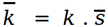 .
Therefore, for a given direction of propagation , the two solutions for discussed above are corresponding to the intersection of the direction of propagation with a sphere and with an ellipsoid.
When propagating in the XY plane, a wave has two different propagation mode, one related to the ordinary index polarized in the XY plane and the other related to the extraordinary index, polarized along Z.
When propagating along the Z axis, the wave has only one propagation mode corresponding to the ordinary index and the polarization is in the XY plane.
.
Therefore, for a given direction of propagation , the two solutions for discussed above are corresponding to the intersection of the direction of propagation with a sphere and with an ellipsoid.
When propagating in the XY plane, a wave has two different propagation mode, one related to the ordinary index polarized in the XY plane and the other related to the extraordinary index, polarized along Z.
When propagating along the Z axis, the wave has only one propagation mode corresponding to the ordinary index and the polarization is in the XY plane.
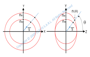
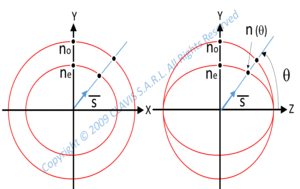 When propagating in any direction making an angle θ with Z, one mode is obviously related to the ordinary index and is polarized in the XY plane, the other is related to the index n( θ ) satisfying the formula :
 .
.
The polarization can be deducted from the formula above giving the electric field regarding the refraction index. As illustrated in the two pictures above, no can be either smaller ( positive uniaxial material ) or larger than ne ( negative uniaxial material ). (Note that the scheme above are wrong because of a scaling issue. Indeed, the curves representing no should be circular)
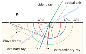 At the interface with a birefringent crystal, two refraction occures : one for the ordinary polarization direction and the other for the extraordinary polarization direction. An incident plane wave is therefore refracted in two directions ( modes ). These directions can be calculated using Huygens method: for each refracted wave, the wavefront is tangent to the corresponding light velocities surface as shown on the graphics beside. Note that the direction of the wave vector for the extraordinary polarization is perpendicular to the wave front and is in general not parallel to extraordinary ray direction.
Birefringent plate
The birefringence is commonly used to control the polarization. Let consider a plane wave propagating in the XY plane and incident on a birefringent plate. Its electrical field can be split in a component in the XY plane corresponding to the ordinary index and another component along Z corresponding to the extraordinary index :
 .
At the plate output, the electrical field is :
.
At the plate output, the electrical field is :
 .
there is a phase shift
.
there is a phase shift  between the two polarizations and the electric field can be written :
 .
If the plate thickness is such that
.
If the plate thickness is such that  (wave plate), the polarization remains unchanged.
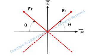 If the thickness is such that
  (half-wave plate) and the incident wave has a linear polarization making an angle θ with the Z axis :
 .
Therefore the polarization remains linear and its direction is symetrical to the incident one regarding Z or
.
Therefore the polarization remains linear and its direction is symetrical to the incident one regarding Z or  .
.
If the thickness is such a that  (quarter wave plate) and the incident wave has a linear polarization making an angle θ with the Z axis :
 .
The wave is then elliptically polarized.
If θ = 45° :
.
The wave is then elliptically polarized.
If θ = 45° :
 .
The polarization is then circular.
.
The polarization is then circular.