Tutorial : gaussian beam - direct coupling
Fiber optic basics
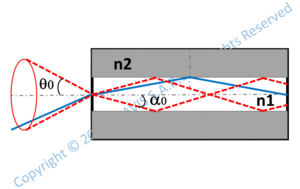 Fiber optics are cylindrical and flexible components guiding light. They are made of a cylindrical core surrounded by a concentric cladding. The refraction index of the core (n1) is larger than the refraction index of the cladding (n2) so that total reflexion can occure at the core/cladding interface. Indeed, total reflexion happens for rays propagating in the core and contained in the cone centered on the optical axis and which half angle is :
 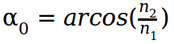 .
.
Therefore, rays contained in this cone may be guided in the fiber optic.  is the numerical aperture and defines the acceptance angle
  .
.
θ0 is different from α0 because of the refraction at the fiber entrance (interface air/core). Note that the formula defining the numerical aperture is suitable for multimode fibers only, the numerical aperture for single mode fibers being defined with the half divergence angle of the gaussian beam with the fiber mode diameter wf (see section below).
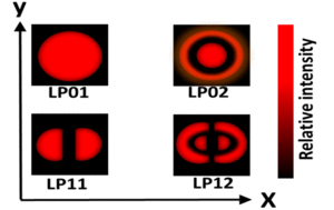 While Total reflexion is a basic and intuitive approach, it is nonetheless unsufficient to explain light wave guiding in fiber optics. To understand light propagation in fiber optics, it is necessary to consider light as an electromagnetic wave. Electromagnetic equations solved with adequate boundaries conditions at the core/cladding interface show that only some specific waves can propagate along the fiber. They are the fiber optic modes and are named LPmq modes. m corresponds the number of intensity minima along the azimuthal axis, while q is the number of intensity minima along the radial axis. Among all possible modes, one specific mode is called the fundamental mode (corresponding to LP01 mode) which is detailed further in this tutrorial. The graphic nearby illustrates schematically the relative intensity of a few low order modes.
One important parameter to charcacterize the fiber optic at a given wavelength is the normalized frequency :
 where R is the core radius and λ is the wavelength. V indicates if the fiber optic is single mode or multimode. Indeed, the fiber optic is single mode if
  and multimode otherwise. Single mode means that the fundamental mode only can propagate. Note that a fiber optic is not intrinsically single mode or mutimode. It is single mode for wavelengths above the cut-off wavelength λc and multimode for wavelengths below λc. λc is defined as follows :
 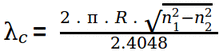 .
.
The normalized frequency V is also suitable to give an approximate value of the number of modes propagating in a highly multimode number :  .
.
 The intensity distribution of the fundamental mode (LP01 mode which is the unique mode guided in a single mode fiber) is close to a gaussian shape :
 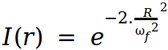 .
.
ωf which is the radius of the fundamental mode can be approximated with following formula :  .
.
ωf is slightly larger than the core diameter. It shows that the fundamental mode propagates mostly in the core but also in the cladding through evanescent waves.
Fiber coupling
Injecting light into a fiber optic is a recurring problem. For a maximum efficiency, the light source etendue has to the as close as possible to the fiber optic etendue. Whatever the optical system used, a quick calculation can give an idea of the maximum coupling efficiency Cmax that can be achieved knowing the respective light source and fiber etendues etens and etenf. In general, the light source etendue is larger than the fiber etendue and : 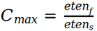 . In the case where etens is smaller than etenf, Cmax = 1. This is for example the case when the light is emitted from a single mode fiber and injected into a multimode fiber which core diameter and numerical aperture (and thus etendue) are much larger.
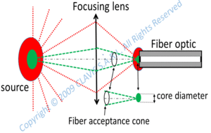 Also, the light source is in general not sufficiently close to the fiber optic for an efficient coupling and an optical system may be necessary to conjugate the light source with the fiber entrance. Only the rays in the fiber acceptance cone coming from a part of the source intercepting the core are injected in the fiber.
An efficient coupling into a single mode fiber can only be achieved with coherent sources (lasers). Indeed, as seen previously, only the fundamental mode LP01 can propagate in a single mode fiber. when propagating in the air, the fiber mode is very similar to a gaussian wave. Therefore, only a gaussian beam is adapted to this wave. Such a spatially coherent beam can be emitted solely by a laser or from a single mode fiber with the same fundamental mode (in which a laser beam has been injected).
In other words, for a maximum coupling efficiency in a single mode fiber, one must use a laser emitting in the fundamental mode only (With a M2 as small as possible). Lasers with large M2 or uncoherent light sources are not suitable for a significant coupling in this kind of fiber optic which core diameter is generally a few microns and numerical aperture is around 0.1 - 0.15. Also, the laser beam has to be shaped in order to fit into the fiber optic core. This means that an optical system may be requested in order to focus the beam waist at the fiber entrance and obtain a beam waist radius as close as possible as the fiber mode radius.
One difficulty when injecting light into a single mode fiber is to focus the laser beam at the exact fiber entrance location. Because the core diameter is very small, the tolerance on the beam positionning is very tight.
Injecting a gaussian beam in a single mode fiber
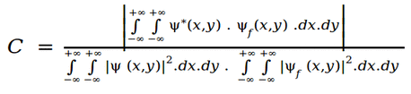
As previously evocated, singlemode fibers request spatially coherent light from a laser. The coupling efficiency is given by the following formula:
 .
.
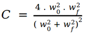
ψ and ψf are the complex amplitude at the fiber entrance respectively of the laser beam and of the fiber mode. The XY plane coincides with the fiber entrance facet. Without any misalignments, which means that the laser beam and the fiber are concentric and the beam waist is located at the fiber entrance, the coupling efficiency becomes:
 .
.
where w0 is the beam waist radius and wf is the fiber mode radius. This formula applies in the ideal case where M2 = 1.
Therefore, this formula shows that the coupling efficiency is optimized when the laser mode and the fiber mode coincide.
The coupling can be optimized in different ways depending on the incident beam.
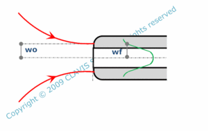
Direct coupling may be a solution as for injecting light from a single mode fiber to another one with the same mode. The coupling ratio can then be close to 100%, especially if the fibers are in contact (the Fresnel reflexions are then very low) or if the fiber ends have anti reflection coatings.
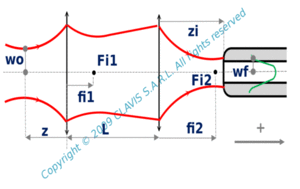
Many lasers have collimated beams with waist dimensions much larger than the fiber mode. They generally request to use a single lens for focusing the waist with an adequate size on the fiber optic entrance. Some laser beams, like VCSEL (Vertical Cavity Surface Emitting Laser) beams have a very small waist located at the emitting surface and have a large divergence. In this case, the emitting surface has to be conjugated with the fiber entrance using one lens but preferably two lenses in order to minimize the spherical aberration: the first lens collimates the beam and the second one focuses it on the fiber entrance. These three common coupling configurations are illustrated in the three schemes below (from left to right: direct coupling, coupling with one lens, coupling with two lenses):

 Whatever the configuration, the coupling efficiency ( C ) decreases when the waist radius ( w0 ) of the
injected beam moves away from the fiber mode radius ( wf ), but also when the beam axis
defocus ( dz ) ( with fiber plane entrance as a reference ), the lateral shift ( dy ) or the tilt ( i ) ( with the fiber axis as a reference )
increase.
Whatever the configuration, the coupling efficiency ( C ) decreases when the waist radius ( w0 ) of the
injected beam moves away from the fiber mode radius ( wf ), but also when the beam axis
defocus ( dz ) ( with fiber plane entrance as a reference ), the lateral shift ( dy ) or the tilt ( i ) ( with the fiber axis as a reference )
increase.