
Tutorial : michelson or similar interferometer - Michelson – tilted mirror - number of equal thickness fringes on a given observation width
Interference with two waves
Young slits
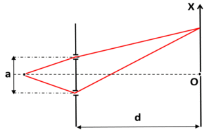
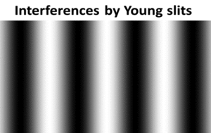
The interference produced by a wave from a punctual source through two holes (or slits) have been described in the section above and the
intensity of the interference pattern on a screen has been approximated as follows :
 .
a is the distance between the holes (or slits), d is the distance frome holes (or slits) to the screen.
.
a is the distance between the holes (or slits), d is the distance frome holes (or slits) to the screen.
It is supposed that  . The fringes are rigorously straights (independant of the height y) with slits and approximately straight with holes in the vicinity of the screen center O. The interfringe is :
 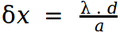 .
So far, it is considered that the intensities of the two interfering waves on the screen are constant which is not true. Indeed, the divergence of the diffracted waves depends on the holes (or slits) dimension. The smaller the holes (or slits) the narrower the diffracted waves. Also, the overlap may not happen if the source is close to the holes (or slits). Whith a source at infinity, the incident wave is plane and the diffracted waves both propagate in the same direction than the incident wave. if the screen is sufficiently far, the overlap happens. The intensity is however strongly decreased out of the diffraction envelope and the fringes are only visible in this envelope.
.
So far, it is considered that the intensities of the two interfering waves on the screen are constant which is not true. Indeed, the divergence of the diffracted waves depends on the holes (or slits) dimension. The smaller the holes (or slits) the narrower the diffracted waves. Also, the overlap may not happen if the source is close to the holes (or slits). Whith a source at infinity, the incident wave is plane and the diffracted waves both propagate in the same direction than the incident wave. if the screen is sufficiently far, the overlap happens. The intensity is however strongly decreased out of the diffraction envelope and the fringes are only visible in this envelope.
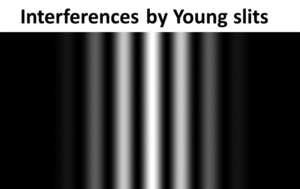 In these conditions, considering slits with a thickness b and taking into acount the diffraction, the intensity on the screen can be approximated by the following formula :
  .
The "sinc" function is the envelope of the diffracted waves.
.
The "sinc" function is the envelope of the diffracted waves.
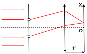 Still using a plane incident wave, the interference can be observed at infinity by placing the screen in the focal plane of a lens (focal length f'). The intensity of the interference pattern is then given by :
 .
The interfringe is :
.
The interfringe is : 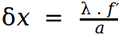 assuming that
  .
.
Michelson interferometer
Other than "Young"'s slits, there are different types of two-waves interferometers. Among them, the Michelson is very common. Note that in this tutorial, Michelson is only presented with monochromatic sources but it can be used also with large spectrum sources (white light sources).
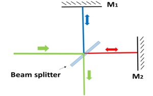 A Michelson includes a beam splitter that divides an incident wave in two waves : one wave is transmitted and the other one is reflected at around 90º. The transmitted and reflected intensities are generally about the same in order to optimize the contrast. Both transmitted and reflected waves are back reflected by mirrors and are recombined by the beam splitter. The two recombined waves can then interfere. Note that about 50% of the incident intensity is not recombined (It is in fact a little bit more because some energy is absorbed by the beam splitter and the reflectivity of the mirrors is lower than 100%).
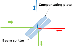 In the device described above, the transmitted wave passes three times in the beam splitter while the reflected wave passes only once. Thus the optical path difference between the two arms is not null when the arms lengths are identical. To overcome this, one place a compensating plate close and parallel to the beam splitter , with the same thickness and the same refractive index than the beam splitter. Both waves pass then through the same glass length and the optical path difference is null when arms lengths are the same.
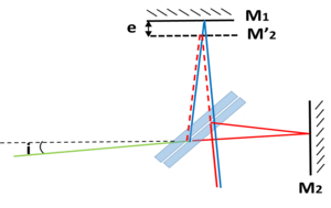 Let consider a monochromatic source placed in the focal plane of a lens so that it is projected at infinity.
Let consider also that the Michelson interferometer is perfectly aligned (the beam splitter angle is exactly 45º regarding the two mirrors which are themselves exactly perpendicular to each other). After recombination, the difference between the optical lengths of the two paths is :
Let consider a monochromatic source placed in the focal plane of a lens so that it is projected at infinity.
Let consider also that the Michelson interferometer is perfectly aligned (the beam splitter angle is exactly 45º regarding the two mirrors which are themselves exactly perpendicular to each other). After recombination, the difference between the optical lengths of the two paths is :
 .
i is the angle of the incident ray with the normal to M2 and e is the length difference between the two arms.
.
i is the angle of the incident ray with the normal to M2 and e is the length difference between the two arms.
The added  is induced by different types of reflexions on the beam splitter. Indeed, air/glass reflexion occur at the division and glass/air reflexion at the recombination. Obviously, the phase shift is constant for incident rays making the same angle i with the axis A1.
If the source is punctual, the incident rays have only one direction and the intensity observed on a screen whatever its position is uniform. In this case, the interference are not located in a defined locus.
is induced by different types of reflexions on the beam splitter. Indeed, air/glass reflexion occur at the division and glass/air reflexion at the recombination. Obviously, the phase shift is constant for incident rays making the same angle i with the axis A1.
If the source is punctual, the incident rays have only one direction and the intensity observed on a screen whatever its position is uniform. In this case, the interference are not located in a defined locus.
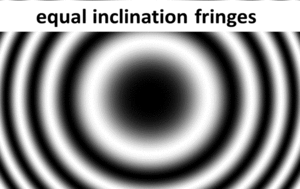 If the source is not punctual, the interference can only be observed at infinity (direcly with the eyes without accommodation or on a screen placed in the focal plane of a lens) as rays with the same direction only can interfere. There is a succession of dark and bright circular fringes, called equal inclination fringes, each fringe corresponding to the interference produced at a fixed angle i with the normal to M2. The intensity distribution at infinity is given by :
 .
.
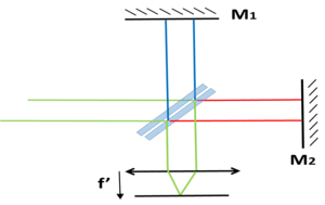 When observed in the focal plane of a lens :
 where f' is the focal length.
The fringe order is defined by
where f' is the focal length.
The fringe order is defined by 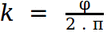 .
.
Thus, it is an integer for bright fringes and half an integer for dark fringes. It decreases with the distance to the axis and is not to be confused with the fringe number counted from the center. The smaller e, the smaller the fringe order. In the case where e = 0, the optical path differences are constant whatever the rays inclination as well as the fringe orders and the intensity is uniform. Because of the different types reflexions on the beam splitter, the intensity is null when e = 0 in the present case.
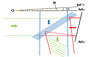
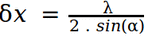
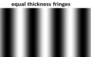 So far, the mirrors of the Michelson were considered perpendicular to each other. Let slightly rotate one of them, for instance mirror M2, with the angle α. The image M'2 of the Mirror M2 by the beam splitter is then making an angle α with M1. With a source at infinity, the Michelson is then producing unlocalized straight fringes, called equal thickness fringes which are parallel to the line O, intersection of M1 and M'2. When observed on a screen parallel to the bissector B toM1 and M'2, the intefringe is :
  .
.
For an extended source, which means that the incident beam is diverging instead of being collimated, the fringes are generally blurred except in the plane parallel to S and passing through L. The fringes becomes localized. However, the contrast decreases when the source dimension increases. The number of visible fringes is approximated by  . δi is the beam divergence. They are counted from the intersection O of the 2 mirrors.
If the source is punctual, interference happen in the same way than in the two "Young" holes experiments. In the present case, the 2 holes are the conjugates of the punctual source by M1 and M'2. The fringes are visible on a screen whatever its position.
Note that equal thickness interference (or air corner interference) are not only obtained with a Michelson. They can be produced for instance by two plates with different angles, the first plate being anti reflection coated on its top face while the second plate is anti reflection coated on the bottom face. The interference come from reflexions on the bottom face of the first plate and on the top face of the second plate. In this configuration, because of glass/air reflexion on the first plate and air/glass reflexion on the second plate, a phase shift of π has to be added to the phase shift calculated from the optical path difference. Air corner interference can also be obtained by two flat mirrors joined and with slightly different inclination. Part of the incident wave is reflected by a mirror while the other part is reflected by the other mirror. Thus, the wave is reflected in two different waves that interfere according to the air corner model presented above.
. δi is the beam divergence. They are counted from the intersection O of the 2 mirrors.
If the source is punctual, interference happen in the same way than in the two "Young" holes experiments. In the present case, the 2 holes are the conjugates of the punctual source by M1 and M'2. The fringes are visible on a screen whatever its position.
Note that equal thickness interference (or air corner interference) are not only obtained with a Michelson. They can be produced for instance by two plates with different angles, the first plate being anti reflection coated on its top face while the second plate is anti reflection coated on the bottom face. The interference come from reflexions on the bottom face of the first plate and on the top face of the second plate. In this configuration, because of glass/air reflexion on the first plate and air/glass reflexion on the second plate, a phase shift of π has to be added to the phase shift calculated from the optical path difference. Air corner interference can also be obtained by two flat mirrors joined and with slightly different inclination. Part of the incident wave is reflected by a mirror while the other part is reflected by the other mirror. Thus, the wave is reflected in two different waves that interfere according to the air corner model presented above.
Interference with a plane parallel plate
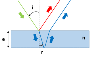 The interference produced by a plane parallel plate with a source at infinity are similar to the intereferences produced by a Michelson with perpendicular mirrors. Indeed, let consider the rays obtained from an incident ray by reflexions on the first and second facets of the plate. The optical path difference between the two reflected rays is
  . r is the refraction angle, e is the plate thickness and n is the refraction index. λ / 2 is induced by the air/glass reflexion on the first facet and the glass/air reflexion on the second facet.
As for the Michelson, interference rings can be observed at infinity and the intensity is :
. r is the refraction angle, e is the plate thickness and n is the refraction index. λ / 2 is induced by the air/glass reflexion on the first facet and the glass/air reflexion on the second facet.
As for the Michelson, interference rings can be observed at infinity and the intensity is :  . It is considered here that the reflexion ratio on the two facets are the same.
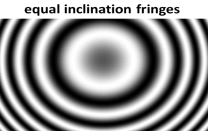 Dark and bright rings are respectively corresponding to the following angles of incidence :
 .
m is the fringe order. it should not be confused with the fringe number counted from the center.
.
m is the fringe order. it should not be confused with the fringe number counted from the center.
When observed in the focal plane of a lens, the radii of the dark and bright fringes are respectively :
 .
The intereferences detailed above are involving reflexions on each facet. Interference by transmission (that is to say interference produced by the transmitted rays and those first reflected by the second facet and then reflected by the first facet) exist also. However, Because of the low reflexion on the facets, their contrast is rather low.
Also, the interference produced by an air gap follows the same rules with a refractive index of 1 and are fully similar to the Michelson case.
.
The intereferences detailed above are involving reflexions on each facet. Interference by transmission (that is to say interference produced by the transmitted rays and those first reflected by the second facet and then reflected by the first facet) exist also. However, Because of the low reflexion on the facets, their contrast is rather low.
Also, the interference produced by an air gap follows the same rules with a refractive index of 1 and are fully similar to the Michelson case.
Newton rings
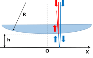 Let consider a curved lens next to a flat plate and a punctual light source at infinity and located on the curve axis which is also the normal to the plate. Intereferences may occur between the two rays issued from a same incident ray, the first one being reflected by the curved surface and the second one by the top facet of the plane plate. The phase shift between the rays is given by the formula below :
 .
h is the gap between the flat and the curved surfaces, R is the radius of the curved surface and x is the distance to the lens axis.
.
h is the gap between the flat and the curved surfaces, R is the radius of the curved surface and x is the distance to the lens axis.
The supplementary phase shift π is included for the reason explained above. This formula works for small values of h and for x that must be much smaller than R. In these conditions, the interference pattern is close to the reflecting surfaces and is made of bright and dark circular fringes called the Newton rings. The radii of dark Newton rings are given by :
 where m is the ring order.
As an example, Newton rings can be used for detecting shape defaults on lenses.
Note that in general, two waves intereference are largely used in metrology and sensing devices. For example, Michelsons are commonly used to make high precision measurements (distances, velocities, refraction indexes,..) but also for spectroscopy like in Optical Coherence Tomography...
where m is the ring order.
As an example, Newton rings can be used for detecting shape defaults on lenses.
Note that in general, two waves intereference are largely used in metrology and sensing devices. For example, Michelsons are commonly used to make high precision measurements (distances, velocities, refraction indexes,..) but also for spectroscopy like in Optical Coherence Tomography...