
Tutorial : diffraction by an optical system - diffraction limit of an optical system
Diffraction basics
The diffraction phenomenom is described by the Huygens-Fresnel principle assuming that every point of a surface illuminated by a light wave can be considered as a secondary source
emitting a spherical wave ( in all directions ). All these spherical waves (wavelets) interfere to generate the diffracted wave.
A consequence of this principle is that a wave going through an aperture (called diffracted wave) has different phase and amplitude distribution than the incident wave. The phase and amplitude distribution
of the diffracted wave depend on the phase and amplitude distribution of the incident wave, on the wavelength, on the aperture shape and dimensions. As an example, a plane wave obturated by an aperture becomes diverging. The smaller the aperture, the larger the divergence. Thus, the irradiance of a plane wave diffracted by a circular aperture and focused on a screen located in the focal plane of a lens is not punctual as stated by the geometrical optics theory. Therefore, the diffraction is an important effect that limits the resolution of any optical system.
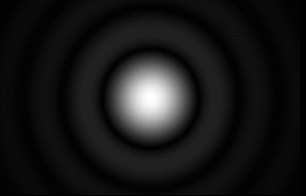
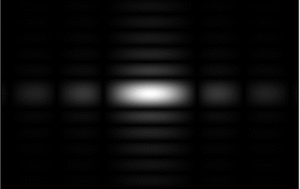 The two pictures nearby show the intensity distribution at infinity (or in the focal plane of a lens) of a plane monochromatic wave diffracted respectively by a circular aperture (left picture) and a rectangular aperture (right picture). Without diffraction, the irradiance pattern should be punctual. As real waves have finite dimensions, plane waves do not exist and all waves have a non null divergence.
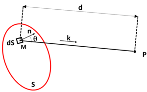 Based on the Huygens-Fresnel principle, the complex amplitude of a wave at a point P of the space is the superposition of the wavelets coming from all points of any surface S crossed by the wave. This complex amplitude is given by the following formula :
  .
M is a point on the surface, ϕa the complex amplitude of the wave at M, k the wave vector, dS a surface element around M, d the distance from M to P and QH, a factor (called inclination coefficient) inversely proportionnal to a distance. This formula is in general not easy to use. There are cases where it can be simplified using some approximations.
.
M is a point on the surface, ϕa the complex amplitude of the wave at M, k the wave vector, dS a surface element around M, d the distance from M to P and QH, a factor (called inclination coefficient) inversely proportionnal to a distance. This formula is in general not easy to use. There are cases where it can be simplified using some approximations.
Fraunhofer diffraction
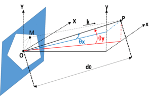 The Fraunhofer diffraction is the particular case for which the wave is monochromatic and the aperture is plane. The surface S mentionned above is then the aperture plane and the point P is located in a plane parallel to the aperture. d0 is the distance between the aperture center O and P. The Fraunhofer approximation applies when d0 is much higher than the other parameters. Then the QH factor can be considered as constant and the formula can be approximated as follows:
  .
.
The complex amplitude can be expressed with the wavelength λ and the angles θx and θy illustrated in the graphic above :  .The intensity is then
  .
The complex amplitude can also be expressed with the parameters ux and uy called the spatial frequencies respectively along the X and Y axis (see MTF tutorial) :
.
The complex amplitude can also be expressed with the parameters ux and uy called the spatial frequencies respectively along the X and Y axis (see MTF tutorial) :  with ux and uy defined as follows :
  For a plane wave propagating perpendicularly to the aperture, the complex amplitude on the aperture is given by its transmittance t(x,y). For example, when the aperture is a simple diaphragm, t(x,y) = 0 around the diaphragm and t(x,y) = 1 inside the diaphragm : in this case, the phase is not changed by the aperture. The simplest cases include a circular or a rectangular diaphragm.
For a rectangular aperture with dimensions a and b respectively along the x and y axis, the normalized intensity is then given by the formula :
For a plane wave propagating perpendicularly to the aperture, the complex amplitude on the aperture is given by its transmittance t(x,y). For example, when the aperture is a simple diaphragm, t(x,y) = 0 around the diaphragm and t(x,y) = 1 inside the diaphragm : in this case, the phase is not changed by the aperture. The simplest cases include a circular or a rectangular diaphragm.
For a rectangular aperture with dimensions a and b respectively along the x and y axis, the normalized intensity is then given by the formula :  For a circular aperture with a diameter D, the intensity has a symetry of revolution around the propagation axis and depends on the angle θ made by the vector OP with this axis :
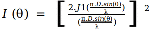 (J1 is the Bessel function of the first kind).
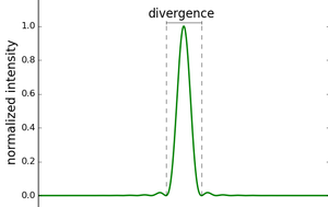 In both cases, the intensity distribution is made of a central pic (for θ = 0) with attenuated lobes as shown on the figure. One can define the diffracted wave divergence by the angular distance between the two first nodes around the pic as most of the energy is contained inside.For a circular aperture, the divergence is the same whatever the plane (XZ or YZ, Z being the propagation axis). For a rectangular aperture, the divergence in the XZ plane depends on the dimension a and the divergence in the YZ plane depends on the dimension b. In the limit case where the rectangular aperture is a slit, the wave is only diffracted in the plane perpendicular to the slit axis.
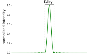 All the optical systems are obturated by an aperture. It can be for example a physical diaphragm like an iris diaphragm used in a camera or a surface of a lens. In general, this aperture is circular. The diffraction by this aperture can be assumed to a Fraunohofer diffraction (at least in the paraxial conditions) and the image of an on-axis point by the optical system (assuming that the optical system is perfect) is not a point but a spot called Airy spot which intensity pattern in the image plane is similar to the intensity pattern observed at infinity (see the figure on the left representing the intensity profile in the image plane). It is given by the formula :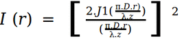
r is the distance to the axis in the image plane and z the distance from the secondary principal plane to the image plane. This formula applies only in paraxial conditions and thus for r much smaller than z. As for the diffraction observed at infinity, the first minima of intensity around the pic circumscribe a disk called Airy disk inside which most of the energy is concentrated. The Airy disk diameter is approximately : 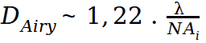 where NAi is the numerical aperture in the image space. The Airy disk diameter can also be calculated with both the focal length of the lens and the aperture diameter in the image space instead of the numerical aperture.
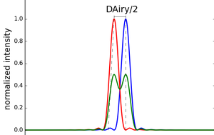 Practically, whatever the optical system quality, it is not possible to obtain an image from a point smaller than the Airy disk. Thus the diffraction is the ultimate resolution limitation of an optical system. The power of resolution is commonly given by DAiry / 2 (Rayleigh criterion). It is considered as the minimum distance between two Airy spots so that they can be distinguished by the human eye. The left figures illustrate the normalized intensity (green curve) obtained by summing the normalized intensity of two Airy spots at a distance from each other of DAiry / 2 (blue and red curves).