Tutorial : single layer - optimal layer thickness vs angle of incidence
Fabry Perot interferometer
The Fabry Perot is certainly the most common interferometer. Indeed, for example, Fabry Perots are used as laser cavities, as spectral filters in the form of thin film deposits and they are part of many high resolution spectroscopic devices.
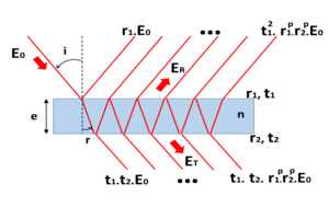 Basically, a Fabry Perot is made of two flat and partly reflecting surfaces. An incident wave is splitted in two waves by the first surface : one is reflected and the other one is transmitted. The transmitted wave is then splitted in two waves by the second surface, one being reflected and the other being transmitted. More generally, when hitting a surface, a wave is splitted in two waves and soforth. Therefore, the wave directly transmitted by the two surfaces can interfere with the wave transmitted after two reflexions, but also with the wave transmitted after four reflexions and so on. In the same way, the wave directly reflected by the first surface interferes with the wave transmitted by the first surface after one reflexion on the second surface, but also with the wave transmitted by the first surface after three reflexions and so on. Finally the reflected and transmitted waves are the superposition of an infinite number of waves.
Considering a plane monochromatic wave, the optical path difference after one round trip between the surface is :
 and the phase shift is therefore :
 .
n is the refraction index, e is the thickness, λ is the wavelength and r is the refraction angle.
depending on the type of reflexions, a phase shift of pi may be added to the initially calculated phase shift and constructive interference become then destructive ones and vice versa. For simplicity, this case is not detailed further as it can be easily deducted from the case without supplementary shift.
The amplitude of the transmitted wave is :
.
n is the refraction index, e is the thickness, λ is the wavelength and r is the refraction angle.
depending on the type of reflexions, a phase shift of pi may be added to the initially calculated phase shift and constructive interference become then destructive ones and vice versa. For simplicity, this case is not detailed further as it can be easily deducted from the case without supplementary shift.
The amplitude of the transmitted wave is :
 .
the transmission and the reflexion are respectively :
.
the transmission and the reflexion are respectively :
 and
and  .
r1 and t1 are respectively the reflexion and transmission coefficients in amplitude of the first surface while r2 and t2 are defined in the same way for the second surface. In the present case, the product r1 . r2 is positive (according to the fact that no extra phase shift is added).
.
r1 and t1 are respectively the reflexion and transmission coefficients in amplitude of the first surface while r2 and t2 are defined in the same way for the second surface. In the present case, the product r1 . r2 is positive (according to the fact that no extra phase shift is added).
 For certain wavelengths
  called the Fabry Perot modes, the transmission is maximum :
  .
.
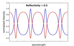
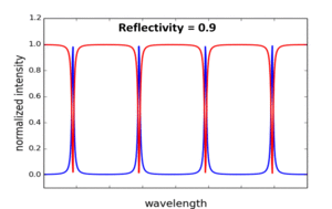
The transmission curve nearby shows that the Fabry Perot behaves as a spectral filter. The blue and red curves represent respectively the transmission and the reflexion coefficients of the Fabry Perot in the case where r1 = r2 = R1/2
The distance between two consecutive modes around the order k in the wavelengths space is :
 .
It can be expressed in the frequencies space as the free spectral range :
.
It can be expressed in the frequencies space as the free spectral range :
 . At normal incidence,
 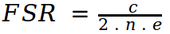 .
The distance between two consecutive modes is therefore constant in the frequencies space.
The finesse of the Fabry Perot relates the spectral selectivity of the Fabry Perot it is defined by the following formula :
.
The distance between two consecutive modes is therefore constant in the frequencies space.
The finesse of the Fabry Perot relates the spectral selectivity of the Fabry Perot it is defined by the following formula :
 , the denominator being the Full Width Half Maximum of the transmission around a mode.
The higher the finesse the more selective the Fabry Perot.
One can remark that the finesse increases when the reflectivity of the Fabry Perot increases.
The disadvantage of the Fabry Perot as a spectral filter is that it is not transmitting one wavelength only but a wavelengths comb. One can overcome this problem by adding a coarse filter that transmit a spectrum centered on a Fabry Perot mode and however sufficiently narrow to "cut" the neighbour modes. More adequately, several Fabry Perot with different thicknesses and refraction indexes and therefore different spectral filtering caracteristics are currently superimposed on a substrate as thin films to achieve many different functions as anti reflexion coatings, high reflexion coatings, narrow band filters, pass band filters,...
, the denominator being the Full Width Half Maximum of the transmission around a mode.
The higher the finesse the more selective the Fabry Perot.
One can remark that the finesse increases when the reflectivity of the Fabry Perot increases.
The disadvantage of the Fabry Perot as a spectral filter is that it is not transmitting one wavelength only but a wavelengths comb. One can overcome this problem by adding a coarse filter that transmit a spectrum centered on a Fabry Perot mode and however sufficiently narrow to "cut" the neighbour modes. More adequately, several Fabry Perot with different thicknesses and refraction indexes and therefore different spectral filtering caracteristics are currently superimposed on a substrate as thin films to achieve many different functions as anti reflexion coatings, high reflexion coatings, narrow band filters, pass band filters,...
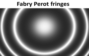 The Fabry Perot can be used also with a diverging source still located at infinity. The interference remain also located at infinity. According to the formulas above, the interference pattern (in reflexion and transmission) is made of dark and bright rings.
The larger the Fabry Perot reflectivity, the larger the finesse and the thinner the bright ring fringes in transmission.
The Fabry Perot can be used also with a diverging source still located at infinity. The interference remain also located at infinity. According to the formulas above, the interference pattern (in reflexion and transmission) is made of dark and bright rings.
The larger the Fabry Perot reflectivity, the larger the finesse and the thinner the bright ring fringes in transmission.
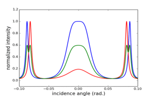 Also, when illuminated with a polychromatic extended light source at infinity, the Fabry perot can spatially separate wavelengths as bright rings corresponding to a given mode have different dimensions depending on the wavelength. Two parameters can then be defined : the phase dispersion
 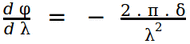 (which is the derived function of the phase with respect to the wavelength) and the power of resolution
  (which is the ratio of the current wavelength on the minimum variation of wavelength distinguishable). According to the Rayleigh criterion, for a given order k, the bright rings related to two different wavelengths are distinguishable if their angular distance is at least the half width to half height of maximum transmission. This case is illustrated on the left side curves. The blue and red curves are the normalized intensities at two wavelengths. The green one is normalized intensity calculated from their sum.
AR coating
AR coatings deposited on refractive substrates are often using multi wave intereferences based on the Fabry Perot Model. They are made of one or several layers. Thanks to an adequate choice of refraction indexes (materials) and thicknesses, they can make the reflexions much lower than the naked substrate.
The reflexions on an air/substrate or a substrate/air interface increase with the substrate refraction index (see tutorial on "polarization"). Without any interference considerations, Adding a coating with a smaller refraction index than the substrate, even if it adds a second reflexion can also significantly decrease the total amount of reflected light. The optimal refraction index of a layer for a minimum reflexion is 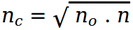 .
.
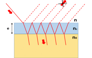 The simplest anti reflexion coatings are made of a single layer. The refraction index and the thickness of the layer are chosen so that the amount of reflected light is minimum on the desired spectral width. These parameteres are calculated using the Fabry Perot model applied to the reflected light.
According to the above formula, the optimal thickness for minimizing reflexions at the a given wavelength is the one for which the intereference by reflexion on the coating are destructive, which means :
The simplest anti reflexion coatings are made of a single layer. The refraction index and the thickness of the layer are chosen so that the amount of reflected light is minimum on the desired spectral width. These parameteres are calculated using the Fabry Perot model applied to the reflected light.
According to the above formula, the optimal thickness for minimizing reflexions at the a given wavelength is the one for which the intereference by reflexion on the coating are destructive, which means :  . Therefore, this thickness is
  where k is a given integer. The thickness depends on the incidence angle and therefore, the anti reflexion coating is working correctly for incidence angles close to the optimum value.
Adding several layers with different thicknesses and different refraction indexes can help to increase the specral band and the efficiency of the anti reflexion. These configurations are not detailed in this tutorial.
where k is a given integer. The thickness depends on the incidence angle and therefore, the anti reflexion coating is working correctly for incidence angles close to the optimum value.
Adding several layers with different thicknesses and different refraction indexes can help to increase the specral band and the efficiency of the anti reflexion. These configurations are not detailed in this tutorial.