photodetection
Photodetection basics
 Photodetectors are optoelectronic components converting light into electrons.
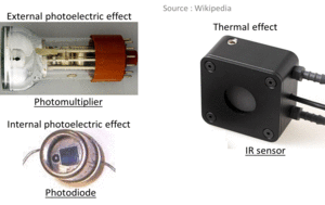
There are three main phenomenom for photodetection : the external photoelectric effect, the internal photoelectric effect and the thermal effect.
Photodetectors are optoelectronic components converting light into electrons.
There are three main phenomenom for photodetection : the external photoelectric effect, the internal photoelectric effect and the thermal effect.
The photoelectric effect applies for detection in the ultra violet, visible and near infrared specral range while the thermal effect applies in the infrared region for wavelengths from around 3 microns up to 30 microns.
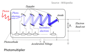 Basically, the external photoelectric effect occurs when a photon strikes a metal or semiconductor placed in vacuum. An electron is then emitted from its surface into vacuum.
Photomultipliers are based on this principle. The electron emitted from the cathode by the incident photon is then multiplied (hence the name) through a system of dynodes with progressive voltage (in the range of a few hundred Volts ) up to an anode. The incident photon energy has to be higher than a threshold depending on the photocatode material. Thus, photons corresponding to wavelengths above a given value can not generate electrons because their energy is not high enough.The final multiplication factor can be very high (in the range of 1 Million for 10 dynodes). Photomultipliers are therefore very sensitive to light and are used for application with low light levels.
In the case of internal photoelectric effect, the sensitive material is a semiconductor. When struck by a photon, an electron goes from the valence band to the conduction band thus creating a hole - electron pair. Then, either an electrical current is generated or the value of an electrical parameter is changed (for instance a resistance change can be induced). These detectors are commonly called quantic photodetectors.
Basically, the external photoelectric effect occurs when a photon strikes a metal or semiconductor placed in vacuum. An electron is then emitted from its surface into vacuum.
Photomultipliers are based on this principle. The electron emitted from the cathode by the incident photon is then multiplied (hence the name) through a system of dynodes with progressive voltage (in the range of a few hundred Volts ) up to an anode. The incident photon energy has to be higher than a threshold depending on the photocatode material. Thus, photons corresponding to wavelengths above a given value can not generate electrons because their energy is not high enough.The final multiplication factor can be very high (in the range of 1 Million for 10 dynodes). Photomultipliers are therefore very sensitive to light and are used for application with low light levels.
In the case of internal photoelectric effect, the sensitive material is a semiconductor. When struck by a photon, an electron goes from the valence band to the conduction band thus creating a hole - electron pair. Then, either an electrical current is generated or the value of an electrical parameter is changed (for instance a resistance change can be induced). These detectors are commonly called quantic photodetectors.
Thermal detectors detect temperature. Indeed, photons in the infrared range heat matter. Therefore, the temperature of a thermal detector increases when illuminated. One of its physical parameters is sensitive to temperature ( for example its electrical resistance ) and changes with temperature changes thus inducing a detection signal.
Quantic photodetectors
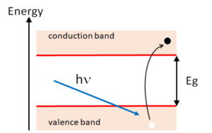 Quantic photodetectors include a semiconductor material. When illuminated, electrons in the valence band can absorb a photon and move to the conduction band. This requests that photons have a higher energy than the energy gap between the two bands.
There are two main types of quantic photodetctors.
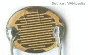 The photoresistance is made of a semiconductor material which resistance changes when illuminated. In the dark, most electrons are in the valence band and the resistance is high. When the illumination level increases, the conductivity increases (the resistance decreases) because more electrons are moving to the conduction band. The conductivity varies generally not linearly with the photon flux. Therefore this kind of detector is not used to detect a flux. It is for instance largely used to detect a threshold illumination level. The photosensisitive zone has a serpentine shape in order to maximize its length in a reduced area and therefore maximize its resistor sensitivity to light.
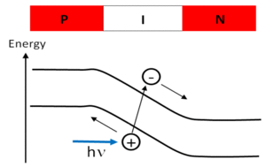 The photodiode is a PN junction. In the dark, its electrical characteristics is the one of a diode, which means that the current is null until the voltage exceeds a threshold value. Above this threshold value, the intensity increases very quickly (the resistance is then very low). When hit by a photon, an electron from the valence band in the junction area absorbs the photon and moves to the conduction band. It is then accelerated by the electrical field in the N doped region and create a current called photocurrent. The condition for the electron to absorb a photon is still that its energy E is at least equal to the band gap energy Eg :
  .
.
As  ( λ is the wavelength, c is the light velocity in air/vacuum and h is the Planck constant ), the condition on the wavelength is :
  .
.
A non null current exists even without any illumination. It is called the dark current. The dark current is induced by thermal effect. It increases both with the applied voltage and obviously with the temperature.
Let consider Np the number of photons per second hitting the photodetector :
 .
.
P is the optical power (expressed in Watts). The probability that an electron absorbs a photon is smaller than 1. Its called the quantum efficiency η. The number of electrons per second absorbing a photon is therefore :
 .
.
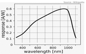 The photocurrent is :
  .
.
R( λ ) is the sensitivity of the photodetector and is expressed in A/W. From the precedent formula, the sensitivity increases linearly with the wavelength up to a value corresponding to the band gap energy. This can be justified by the fact that the larger the wavelength, the more photons are requested for the same power and thus the larger the current.
In reality, the quantic efficiency depends also on the wavelength and the sensitivity is therefore not linear regarding the wavelength as shown on the curve.
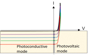 The two functionning modes of a photodiode are the photoconducting mode and the photovolotaic mode. As depicted on the curve, the photoconducting mode is when a reverse voltage is applied and the product of the voltage by the current is therefore positive. In this case, the current increases linearly with the luminous flux and is suitable for light detection. In the photovoltaic mode, the product voltage by current is negative and the device produces energy. It is for example the case of the pholvoltaic cells.
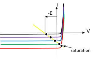 Because the dark current and thus its noise (see the "noise" section) increase with the applied voltage, low light level are preferably detected without any applied voltage. This regime is at the border between photovoltaic and photoconductor mode. Because the saturation level increases with the voltage, it is nonetheless preferable to apply a voltage when detecting high light levels.
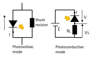 Ideally, the resistor of the photodiode is infinite. In reality, it is not. It is called the shunt resistor. The shunt resistor increases with temperature. The higher the shunt resistor the more the photodiode is sensitive to low light levels.
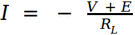
In photoconductor mode, the signal is detected through a resistor called the load resistor RL connected in series with the photodiode. The voltage Vs and current I across the load resistor are given by :
Ideally, the resistor of the photodiode is infinite. In reality, it is not. It is called the shunt resistor. The shunt resistor increases with temperature. The higher the shunt resistor the more the photodiode is sensitive to low light levels.
In photoconductor mode, the signal is detected through a resistor called the load resistor RL connected in series with the photodiode. The voltage Vs and current I across the load resistor are given by :
 ,
,
 .
.
V is the voltage across the photodiode and E is the applied voltage.
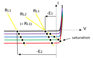 The larger the voltage applied or the lower the load resistor, the higher the saturation level.
The higher the load resistor, the higher the signal voltage and therefore the sensitivity to low signal levels.
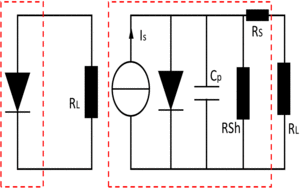 When used for detecting modulated light, a photodiode has a limited bandwidth.
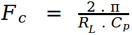
This limitation can be explained by adding to the photodiode scheme an equivalent capacity (internal capacity) Cp connected in parallel. The cut-off frequency is then :
When used for detecting modulated light, a photodiode has a limited bandwidth.
This limitation can be explained by adding to the photodiode scheme an equivalent capacity (internal capacity) Cp connected in parallel. The cut-off frequency is then :
 .
.
It is the frequency above which the signal contrast is smaller than 0,5 (3 dB attenuation) and defines the bandwidth of the photodiode.
The internal capacity decreases when the detector size decreases and when the applied voltage increases.
The bandwidth is not intrinsic to the photodiode as it depends not only on the internal capacity but also on the load resistor.
The higher the load resistor, the lower the bandwidth. Note that in the equivalent sheme, a series resistance (Rs) is also to be added.
Thermal photodetectors
There are three main types of thermal photodetectors : the thermopiles, the bolometers and the pytoelectric detectors.
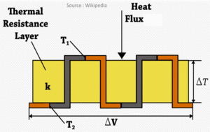 Thermopiles are made of thermocouples connected in series. A thermocouple is made of two different conductive materials that are soldered at one end. An absorbing layer is deposited on this junction and is heated when exposed to infrared radiations. Because of the temperature difference between the two ends of the conductive materials (one is heated and the other not), a voltage is created (Seebeck effect) which is proportionnal to the temperature difference and therefore to the heat radiation. Thermocouples don't request any bias voltage.
Bolometers use materials which resistivity depends on the temperature and therefore on the heat that has been absorbed. By applying a voltage across the resistor, any resistivity change is transformed in a current change depending on the variation of absorbed heat. These kind of thermal detectors are very sensitive. Among others, they are used in scientific and military applications.
Pyroelectric detectors use dielectric crystals (which are insulators) in which a temporary voltage appears when heated. This voltage is transient and disappears after a certain time called the dielectric relaxation time. Therefore, pyroelectric detectors can only detect modulated radiations. They can be used for instance to detect any intrusion or to measure the energy of a laser pulse.
Noise in photodetectors
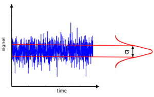 A photodetector provides a signal with small fluctuations. These fluctuations are the noise of the photodetector. The noise is randomatic and therefore can not be predicted.
It is given by the variance of the signal :
A photodetector provides a signal with small fluctuations. These fluctuations are the noise of the photodetector. The noise is randomatic and therefore can not be predicted.
It is given by the variance of the signal :
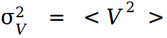 if the signal is a voltage or
 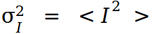 if it is a current.
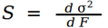
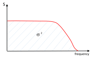 The noise depends on the fluctuations frequency. Therefore, it is more precisely caracterized by its spectral density corresponding to the derivative of the variance by the fluctuations frequency :
  .
.
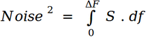
The total noise is limited to the photedector bandwidth ΔF. Thus, it is calculated with the integral of the spectral density on the bandwidth range :
 .
.
The obtained value is homogeneous to the squared signal and is thus the squared noise.
The noise can be lowered for example by limiting the bandwidth and thus cutting the high frequencies contribution.
Different noises
There are different sources of noise.
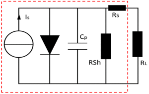 As detailed in the previous section, a semiconductor photodetector can be modellized by a theoretical current source connected to a perfect diode in parallel with a capacitor and a shunt resistance. It is depicted on the left-side scheme.
The first one is the shot noise. The shot noise is induced by the intrinsic quantic behaviour of light which is considered as a set of photons hitting the photodetector with randomatic time laps. The shot noise is defined by its spectral density which is :
 .
.
IS is the signal current (generated by light detection) and q is the electron charge.
The shot noise is the ultimate detection limitation. Indeed, it applies whatever the photedector (even it is noise free which is not realistic).
The shot noise applies not only to the signal but also to the dark current. The dark current ID is a leakage current induced by thermal agitation as detailed in the "quantic photodetectors" section. It has a randomatic flow and it creates a noise (dark current noise) similar to the shot noise induced by the signal and caracterized by the its spectral density :
 .
.
The shot noise applies also to the luminous background if any producing a current IB. Thus, the total shot noise is :
 .
.
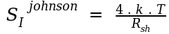
The Johnson noise or thermal noise is the noise induced by the thermal agitation of the carriers in the shunt resistance and is caracterized by its spectral density :
 .
.
k is the Boltzman constant and T is the temperature (in Kelvin). Note that Johnson noise is also induced in the load resistance if any.
The Flicker noise is caused by slow fluctuations of the carriers in the semiconductor and is negligible for frequencies in the range of a few kHz. It is mainly induced by the photodetctor technology.
Noise Equivalent Power (NEP)
The Noise Equivalent Power (NEP) is defined as the optical power such that the signal to noise ratio is equal to 1 for a 1 Hz frequency bandwidth. It depends on the wavelength and is expressed in Watts per square roots of frequency.
Therefore, the associated signal current is :
 .
.
For a photodetector with a bandwidth ΔF, the optical power requested for achieving a signal to noise ratio of 1 is :
 .
.
At the wavelength λ, the NEP is:
 .
.
λpeak is the wavelength corresponding to the highest sensitivity.
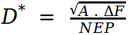
Sometimes, the photodetectors manufacturers specify the specific detectivity :
 .
.
A is the area of the sensitive surface. As the NEP depends linearly on the square root of A, D* provides a normalized caracterization of the photodetor.
Signal To Noise Ratio (SNR)
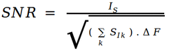
The different noises (each caracterized by its current spectral density SIk ) are decorrelated from each other. The signal to noise ratio (SNR) is thus :
 .
.
IS is the signal current.
When shot noise and Johnson noise are overriding :
 .
.
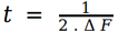 is the integration time.
In the case where the SNR is limited by the Shot noise (no Johnson noise) :
 .
.
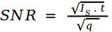
The highest value of the SNR is obtained for a noise free detector including a null dark current. The SNR is then :
 .
.
It is only limited by the shot noise of the signal. However, it is a theoretical case.
In the case where the NEP of the photodector is provided, SNR = 1 is achieved for an optical power equal to the NEP and an integration time of 0.5 s (corresponding to a frequency bandwidth of 1 Hz) :
 .
.
where Sdet is the spectral density of all intrinsic noises of the photodetector. Sdet is useful for any SNR estimation and can be calculated from the last formula :
 .
.
Case of Infrared detectors
For the IR detectors, the background noise comes from the radiations emitted by the surrounds. These radiations come for instance from the detector packaging, from the eventual optics and mounts, from the detector itself which therefore may request to be cooled...
Ideal thermal detectors ( BLIP : "Background Limited Infrared Photodetector") are considered to be limited by this background noise. Considering that the background flux is produced by a black body at a given temperature T and is viewed by the detector through a given angular field of view α, its value is :
 .
.
LB is the background radiance.
The noise equivalent power is therefore :
 .
.
The specific detectivity D* can be deducted from the NEP :
 .
.
D* depends on the quantum efficiency of the material, on the wavelength, on the field of view and on the temperature of the background (through the radiance - see "black body" tutorial).
Case of CMOS and CCD cameras
CMOS and CCD cameras are semiconductor based (Silicium) cameras. Each pixel is a photodetector. The principal noises that can be easily calculated are the shot noise, the dark current noise and the read out noise. The read out noise is created during the different read out steps of the pixel starting from the analog to digital conversion up to the image production. The read out noise is generally given as a number of electrons. It is independant from the integration time but is generated during each exposure. It means that if the image recording requests several exposures (for instance because the maximum exposure time is smaller than the integration time requested to obtain a suitable image), the total read out noise is the read out noise for one exposure multiplied by the square root of the exposure number m.
Therefore, considering that NpS is the number of photons per second of interest (providing the signal), NpB is the number of photons from the background, ND is the dark current expressed in e-/s and Ron is the read out noise expressed in e- :
 .
.
imaging sensors
An imaging sensor is the photons sensing component of a camera and is made of a matrix of photodetectors called pixels. Depending on the spectral range, sensors are based on different technologies and materials. CMOS and CCD ( using Silicon) are common in the UV-VIS-NIR (Ultra Violet, Visible, Near-Infrared). InGaAs based sensors are widely used in the SWIR (Short Waves Infrared) and micro bolometers are very common for longer wavelengths in the infrared.
The quality of an imaging sensor is related to its sensitivity and its spatial resolution. The spatial resolution depends on the pixel size but also on the possible cross-talk between adjacent pixels as pixels are in general very close to each other.
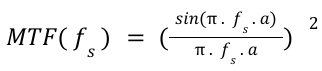
The spatial resolution of an ideal imaging sensor (without cross-talk) is limited by the pixel size and is given by the Modulation Transfer Function representing the contrast of the sensor depending on the spatial frequency (number of dark and brilliant lines per mm) of the target. For a target made of lines with a sinusoidal normalized intensity from 0 to 1 at a spatial frequency of fs, the maximum contrast obtained on a camera with a pixel size of a is:
References
"Cours détection dans le domaine optique" - Ecole Nationale Supérieure des Télécommunications - 1988 - author : P. Gallion.
"Détecteurs Optiques et Introduction aux systèmes optroniques" - Licence Pro. Instrumentation Optique et Visualisation (Université Pierre & Marie Curie) - author : J. LAURAT.
"Notes bruit dans un photodétecteur large bande" - Laboratoire Collisions, Agrégats et Réactivité, CNRS - 2008 - author : G. Bailly.
"Cours bruit et limite de détection" - Ecole Polytechnique Fédérale de Lausanne - 2002 - author : P.A. Besse.