Optical software
Introduction
The Optical software is a versatile tool that allows for more complex computations than the Handy Calculations pages. It focuses on the analysis and optimization of optical systems and simulates real ray propagation. In addition, paraxial and radiometric calculations are available, as well as modeling for laser beam propagation and fiber coupling.
Almost any type of system can be simulated — up to 22 surfaces can be defined. Various surface types are supported: spherical, conical, aspherical, toroidal, biconical, paraxial, and paraxial without rotational symmetry. Gratings are also supported in both transmission and reflection. Surfaces can be tilted and decentered. Moreover, components from catalogs can be imported directly for simulation.
The aperture can be defined using different criteria: numerical aperture, half-angle, surface diameter, and f-number. Its position is defined by a specific surface within the system. Alternatively, the system can be telecentric in either the object or image space. Circular and rectangular apertures/obscurations are supported and can be decentered.
Up to 7 different wavelengths and 7 different fields can be defined.
Radiometric calculations can be performed using various source types (including blackbodies and grey bodies) with different shapes: point, circular, rectangular, cylindrical, and annular.
Numerous options are available for both calculations and results display. Input data can be saved locally on the user's computer (note: no data is stored on the "optical-calculation.com" server).
A wide range of analysis and optimization features are available.
Among other capabilities, the software can perform 3D texture ray tracing, spot diagrams, ray aberration analysis, wavefront error evaluation, point spread function (PSF), and modulation transfer function (MTF) analysis. It can also evaluate the optimal position of the observation surface based on spot size.
Additional features include paraxial and chromatic aberration analysis, as well as evaluation of the power transmitted from a light source. Laser beam propagation and coupling efficiency into single-mode or multimode fibers are also supported.
Numerous surface parameters and merit function criteria can be used for optimization.
Overview
The "Optical software" can be accessed by clicking the Optical software button once on the Access page.
On the landing page (and all pages of the software), an horizontal menu is displayed:
- (1) undo/redo buttons.
- (2) access to the "save - upload" page (which is the landing page by clicking on the Optical software button).
- (3) drop-down menu for editing and entering all system input parameters.
- (4) drop-down menu to access to all catalogs (glasses and components).
- (5) Buttons and menus to access all calculations (analyzis features and optimization).
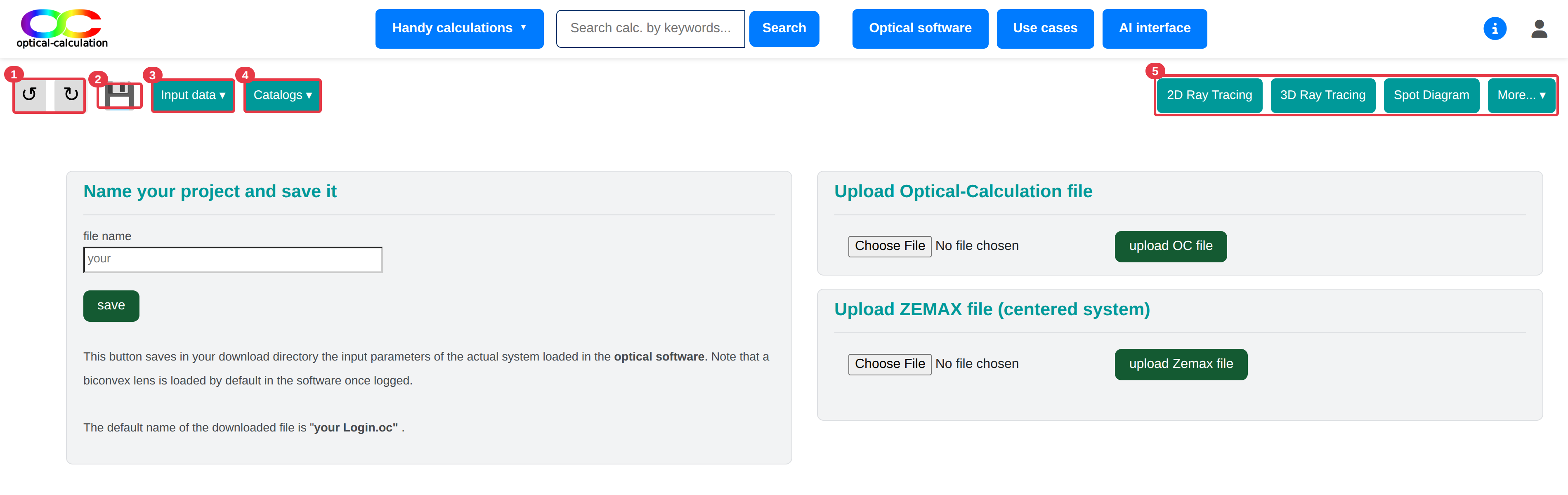
The landing page is used to save the optical system data currently loaded into the software or to upload a system from a file. Further details on saving and uploading are provided in the relevant section. Note that a biconvex lens is loaded in the software by default.
Input data menu (3)
This drop dow menu includes provides access to pages for editing and entering parameters:
- "Number of surfaces" (to set how many surfaces the system has),
- "Surfaces parameters" (to enter parameters for each surface),
- "Aperture and fields" (to define aperture and field positions),
- "Wavelengths" (to define the wavelengths used),
- "Light source" (to define radiometric or laser parameters),
- "Fiber optic" (for fiber coupling calculations),
- "Detector" (to define detector parameters for full MTF analysis),
- "Optimization" (to define optimization parameters as variaiables, merit functions and boundaries),
- "Settings" (to define options and additional parameters for calculations or display),
- "Surfaces management" (to add, remove, or flip surfaces),
- "Insert a component" (to insert or replace a system with a catalog component),
- "Quick set-up" (for directly defining a complete system using catalog components).
Catalogs menu (4)
This drop dow menu provides access to glasses and components catalogs:
- "Glasses" (to set how many surfaces the system has),
- "Lenses" (to enter parameters for each surface),
- "Mirrors" (to define aperture and field positions),
- "Gratings" (to define the wavelengths used),
- "Prisms" (to define radiometric or laser parameters),
- "Windows" (for fiber coupling calculations).
Calculations processing buttons (5) (2)
This section combines buttons providing quick access to the most commonly used analysis features ("2D Ray Tracing", "3D Ray Tracing", and "Spot Diagram"), along with a drop-down menu organized by category that provides access to all analysis and optimization features.
Here is the drop-down menu break-down:
PARAXIAL
- "conjugation" (paraxial image and system parameters),
- "longitudinal chromatism" (image position vs. wavelength),
- "aperture" (paraxial aperture in object/image space),
- "laser beam propagation" (paraxial laser beam analysis).
REAL PROPAGATION
- "2D ray tracing",
- "3D wireframe ray tracing",
- "3D texture ray tracing",
- "single ray propagation",
- "spot diagram",
- "full field spot diagram",
- "ray aberration",
- "encircled energy",
- "distortion",
- "table WFE",
- "surface WFE",
- "MTF",
- "full MTF",
- "PSF",
- "PSF cut-out",
- "best focus",
- "relative laser beam intensity-text",
- "relative laser beam intensity-map",
- "relative laser beam intensity-cross",
- "vignetting",
- "SAG".
RADIOMETRY
- "transmitted flux" (calculates transmitted power from a light source).
FIBER OPTICS
- "laser coupling in a single mode fiber optic",
- "laser coupling in a multimode fiber optic".
OPTIMIZATION
- "DLS cycles" (Damped Least Squares optimization),
- "DLS-cycles-random" (same, from randomly selected starting points).
"Input data" pages
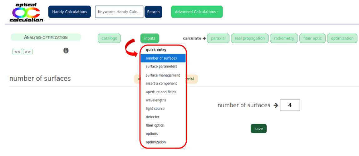
Each link in the "Input data" menu leads to a page containing the following elements:
- One or more tables for entering parameters,
- Contextual support via the beige buttons ("About", "Caution", and "Tutorial") located at the top of each table for better understanding and usability.
Input tables
The input tables vary from page to page. They may include different types of input fields: text fields, checkboxes, dropdown menus, and radio buttons.
Parameters are only saved after clicking the corresponding "Apply" button. If multiple tables are present, you must click "Apply" for one table before entering data into another. Do not input data into multiple tables and click all "Apply" buttons afterward — this could result in incorrect behavior.
The image below shows the page used to define the system aperture and fields.
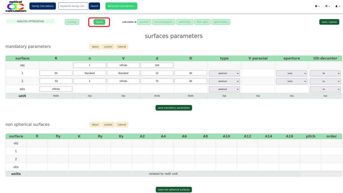
The maximum number of characters allowed depends on the parameter type, with a general limit of 14 characters. Consequently, the maximum number of decimals is also limited — up to 13 for positive numbers and 12 for negative ones in standard notation.
Scientific notation can be used to bypass these limits (e.g., you may enter 1.23e-12 instead of 0.00000000000123).
Exception: "Surfaces parameters" page
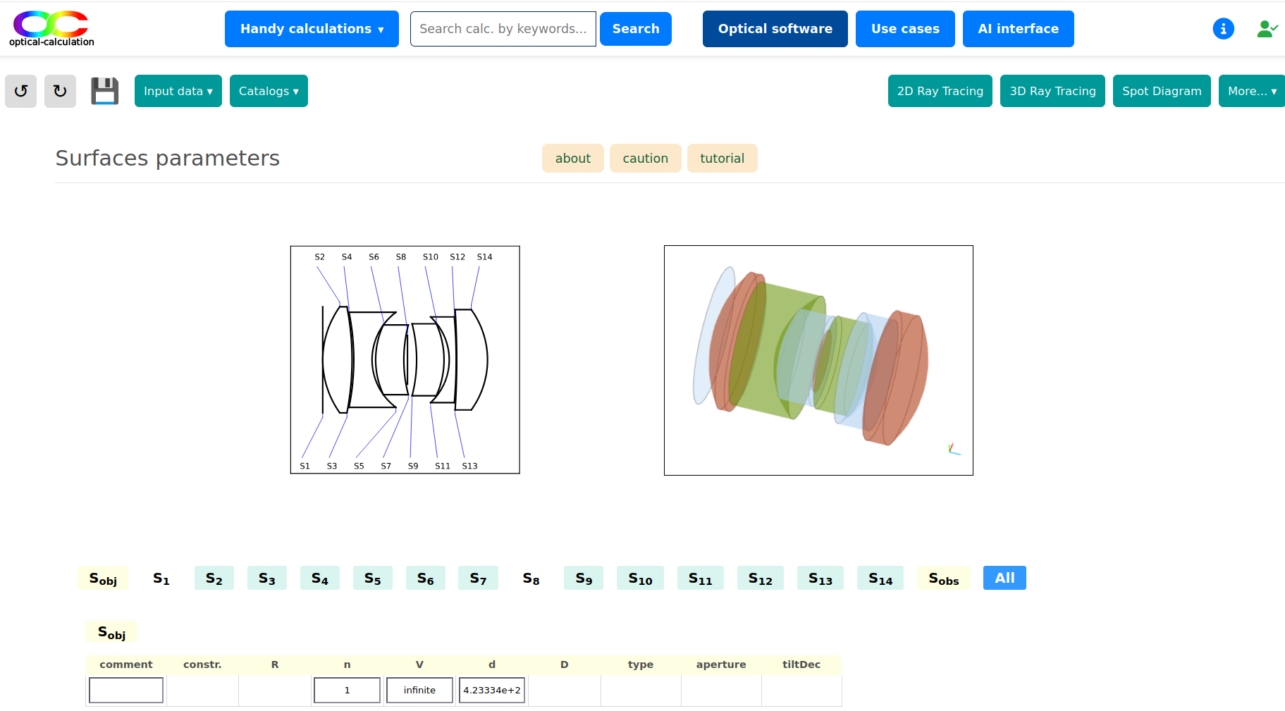
When possible, 2D and 3D views of the optical system are displayed at the top of this page. Buttons labeled "Sx" (where "x" is the surface number) are displayed below. Unlike other pages, this one does not display all input tables by default.
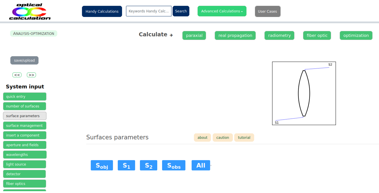
Clicking on a "Sx" button displays the table for the corresponding surface. Clicking the same button again hides the table. This allows you to show/edit only the parameters of the desired surfaces.
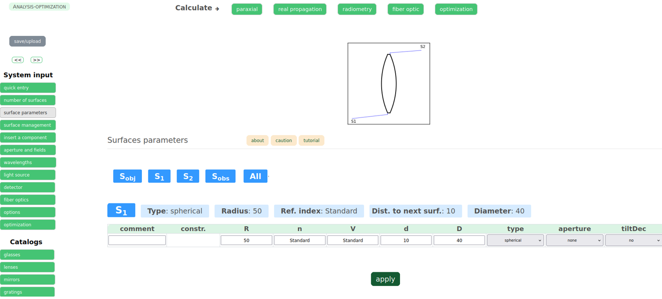
The "All" button displays all surface tables at once and hides them again if clicked a second time.
Each surface has a table with at least one row of mandatory parameters (e.g., radius of curvature, refractive index and constringence of the next medium, distance to the next surface). Other rows are revealed by selecting surface types, aperture types, tilts, and decentering options.
It's also possible to constrain one surface relative to another. In that case, an additional row is displayed to define the relationship between the surfaces.
Contextual support
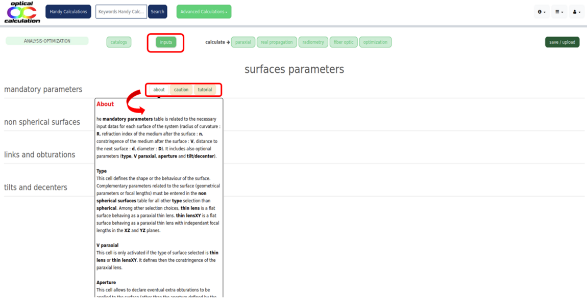
Each input table includes contextual support. When hovering over the beige "About" and "Caution" buttons at the top of the table, tooltips appear with additional information.
These can also be displayed in a separate page by clicking the buttons.
- "About" explains the different parameters in the table.
- "Caution" gives guidance on how to properly enter the parameters.
- The "Tutorial" link opens a detailed guide about the relevant input page in a separate page.
Input parameter entry order
A default system (a single lens) is loaded automatically when logged. If your system is different, you should define the main parameters in the following order:
1) Number of surfaces (via "number of surfaces"),
2) surface parameters (to be entered in "surfaces parameters" page),
3) Aperture (via the "aperture" table in "aperture and fields" page ),
4) Fields and wavelengths (respectively the "fields" table of the "aperture and fields" and the in the "Wavelengths" page).
This order helps avoid inconsistencies. Errors or conflicts are detected as you enter data. All other parameters can be entered in any order.
"Catalogs" pages
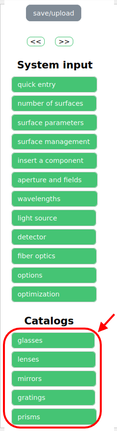
Catalogs are accessible via the "catalogs" dropdown menu, which offers access to six different catalogs: "glasses", "lenses", "mirrors", "gratings", "prisms" and "windows".
Catalog tables
Regardless of the selected element type ("glasses", "lenses", "mirrors", "gratings", "prisms" or "windows"), a selection table appears on the left side of the page. This table allows you to filter references using various criteria.
Once the selection table is validated, the matching elements are displayed in a result table on the right, along with their main characteristics.
Note that all catalogs are available to every user for consultation. Logged-in users with a "Premium license" gain access to complete catalogs for simulation purposes, while those with a "Free license" only have access to reduced versions.
References that can be used for simulation are marked with a green open padlock (), while references that are view-only are marked with a red closed padlock(). The number of references per component type and per license type are given in the features page.
Contextual support
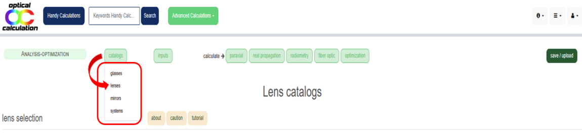
Each "catalog" page includes contextual assistance. Tooltips with information related to the specific catalog appear when you hover over the beige "About" and "Caution" buttons at the top.
These tooltips can also be opened in a separate page by clicking on the respective buttons.
- "About" explains the different parameters found in the selection and result tables.
- "Caution" provides recommendations for correctly entering filter criteria in the selection table.
- The "tutorial" link opens a detailed guide on the chosen catalog and offers practical tips for component selection.
"Save / upload" button
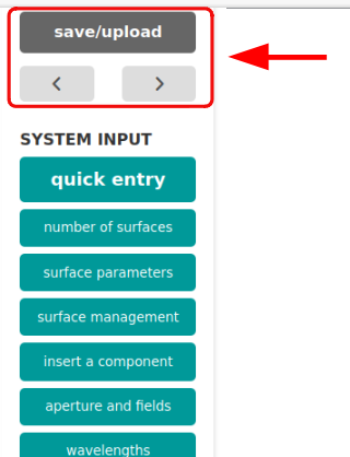
You can save or upload input parameters used in the "Optical software" by clicking on the button with a floppy disk icon (2).
To the left of this button, two additional buttons (1) allow you to load the previously saved setup or move forward to the next one.
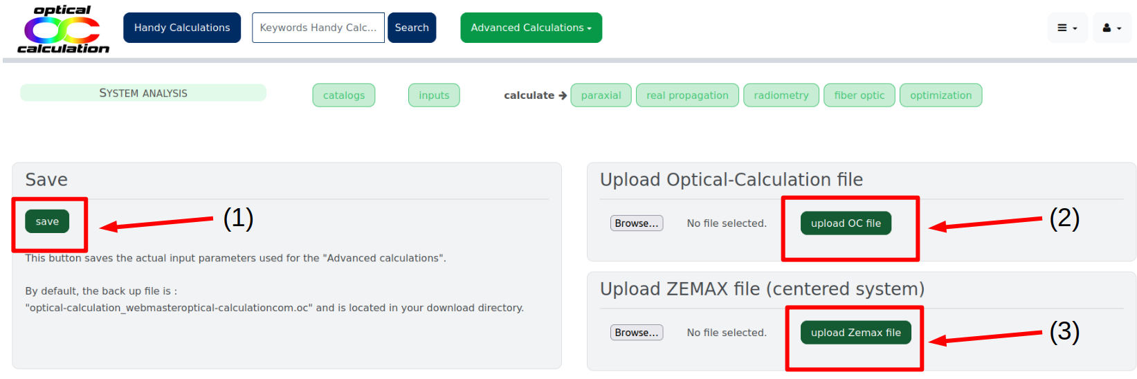
Clicking the button with a floppy disk icon (2) opens a "save/upload" page with three sections:
(A) A section on the left with a "save" button,
(B) A section on the right for uploading an OC file,
(C) A section below for uploading a Zemax file.
Remember that this page is also the default landing page of the software.
Saving the actual configuration
The quickest way to save your input parameters is to click the "save" button directly. The parameters are then downloaded to your computer’s "Downloads" folder as a file named optical-calculation_"userLogin".oc, where "userLogin" is a simplified version of your email (dots and @ removed).
You can also enter a custom filename in the designated field before clicking "save".
Uploading an OC file
Input data can be uploaded from a previously saved file on your computer. To do this, select the file using the "Browse..." button in the "Upload Optical-Calculation file" section, then click "upload OC file".
⚠️ For maximum privacy, saved files are never stored on the "optical-calculation.com" server but on your computer.
Uploading a Zemax file
You can also upload a .zmx file (Zemax format) by selecting it via the "Browse..." button and clicking "upload Zemax file" in the "Upload ZEMAX file (centered system)" section. This feature currently does not support coordinate breaks, so it is intended for centered systems only.
If your Zemax file fails to upload, please contact us — this is often due to a glass reference mismatch between your Zemax file and our database, or a reference missing from our catalogs. In both cases, we can adjust our database accordingly.
Important: To avoid losing your data, we strongly recommend saving your input parameters regularly. These data are lost once your session expires.
Output pages
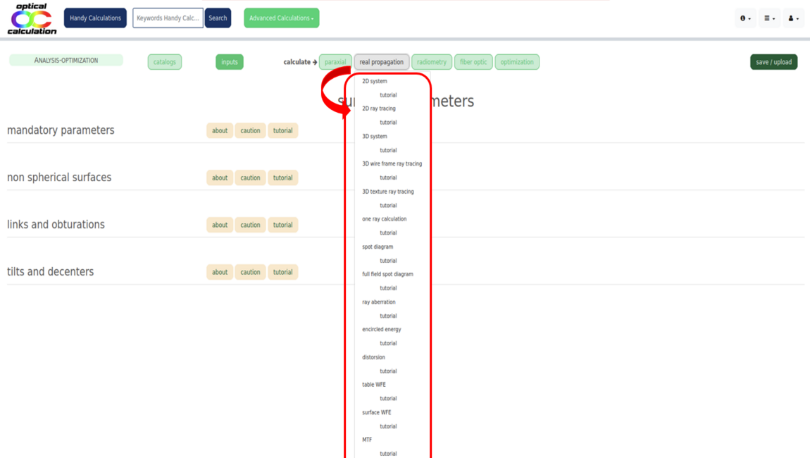
A calculation is executed by clicking the corresponding button in the "More..." dropdown menu or by directly clicking on a separate button ("2D ray tracing", "3D ray tracing", "Spot diagram") if one of them is relevant. Depending on the type of calculation selected, the result is displayed as a graph, a table, or plain text.
A tutorial is available for each calculation via the "tuto" link to the right of the corresponding button in the "More..." menu. The tutorial explains how the calculation is performed and provides information about optional settings that can be used to customize the process.
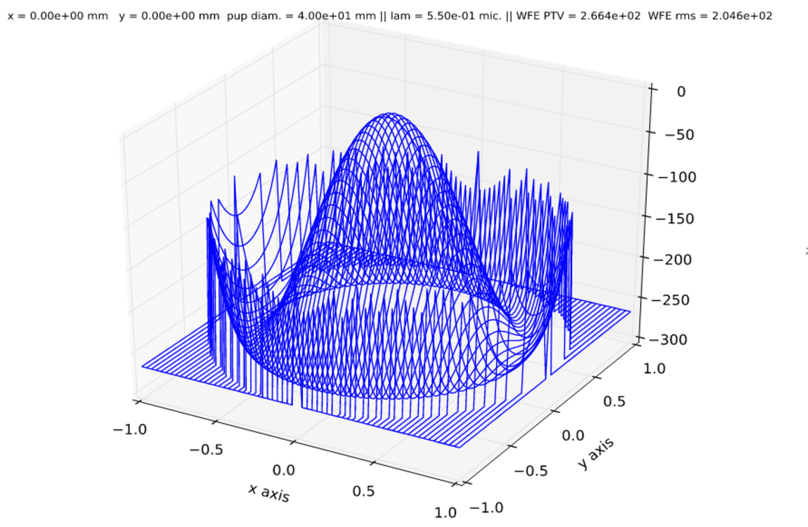
The image below shows a surface representing the Wave Front Error of a system (for a given field and a given wavelength) as a fonction of the rays positions on the aperture.